In structural steel, prequalified welding procedures initiate the system of Welding Procedure Specifications (WPS) qualification and are usually substantiated further with standard qualification and mock-up tests. Prequalified welds must pass the initial testing in order for construction to proceed, while failing the tests requires the engineers to modify and repair their materials before they can continue with the project.
A prequalified weld conforms to technical qualities required by necessary welding requirements as specified by structural codes. In this blog post we will explore how to understand prequalified welds symbols in steel structure.
Recommended for you: Types of welds in steel structures.
Importance of Prequalified Weld Symbols
- Clear Communication: Weld symbols provide a standardized method of communicating welding requirements and specifications between engineers, designers, and welders. This ensures everyone involved in the welding process understands the intended procedure and meets the necessary qualifications.
- Consistency and Compliance: By following prequalified weld symbols, welding operations can adhere to recognized welding codes and standards, ensuring compliance with industry regulations. This consistency promotes uniformity in welding practices, reducing the risk of substandard welds and potential failures.
- Quality Assurance: Prequalified weld symbols help maintain quality control by providing a visual representation of the required weld dimensions, joint configurations, and acceptance criteria. Welders can refer to these symbols to ensure they meet the specified standards and produce sound welds.
Don’t miss: Exploring the Various Types of Weld Positions
Basic groove weld symbol
According to the American Welding Society (AWS) D1.1 Structural Welding Code – Steel, the basic weld symbol consists of several elements that convey important information about the welding process. Here is a breakdown of the basic weld symbol as per AWS D1.1:
Symbol of weld types
| 1 | Square Groove |
| 2 | Single V-Groove |
| 3 | Double V-Groove |
| 4 | Single Bevel Groove |
| 5 | Double Bevel Groove |
| 6 | Single U-Groove |
| 7 | Double U-Groove |
| 8 | Single J-Groove |
| 9 | Double J-Groove |
| 10 | Flare Groove |
| 11 | Flare Groove (Open Root) |
| 12 | Flare Bevel Fillet |
Symbols for joint types
| B | Butt Joint |
| C | Corner Joint |
| T | T Joint |
| BC | Butt or Corner Joint |
| TC | T or Corner Joint |
| BTC | Butt, T or Corner Joint |
Symbols for weld process
| F | FCAW |
| G | GMAW |
| sc | Short Circuit |
| S | SAW |
| Note of any of the above | SMAW or GTAW |
Symbols for base metal thickness and preparation
| U | Unlimited thickness, Complete Joint Penetration |
| L | Limited thickness, Complete Joint Penetration |
| P | Partial Joint Penetration |
Common groove welds in steel structure
The most common about 95% used groove welds are as follows.
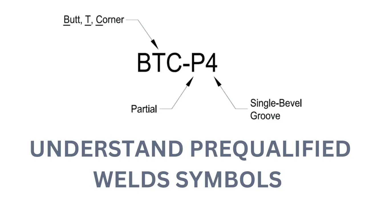
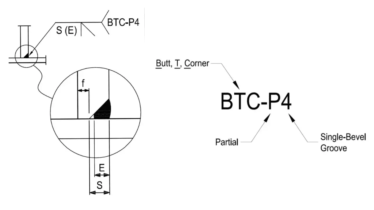
1. BTC-P4
| Fig. 1: BTC-P4 weld designation |
S= Preparation (Bevel)
f= Land, 1/8″ (minimum)
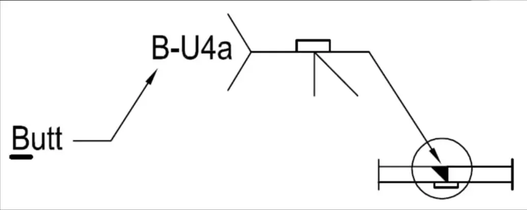
2. TC-U4a
| Fig. 2: TC-U4a weld designation |
| Fig. 3: BC-4a weld designation |
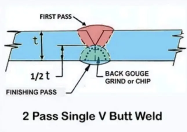
| Fig. 4: Backgouge in weld |
a= Backing bar
b= Backgouge
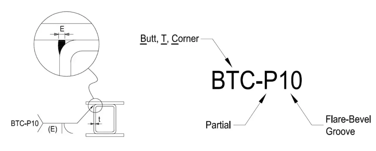
4. BTC-P10
| Fig. 5: BTC-P10 weld designation |
Final Words or conclusion
Prequalified weld symbols serve as a language of their own, providing valuable information about the welding procedure, acceptance criteria, and compliance with industry standards.
Understanding these symbols is essential for welders, inspectors, and engineers involved in welding projects. By decoding prequalified weld symbols, we can ensure clear communication, consistency, and quality assurance in the welding process, ultimately leading to the production of reliable and safe welded joints.
